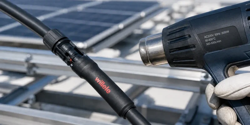
A photovoltaic array is engineered to run outdoors, unattended, for a quarter of a century. Panels, inverters, and mounting rails are selected with that lifespan in mind — yet the electrical joints that bind them together are often protected by a sleeve of tubing that costs little. That sleeve is where термоусадочная трубка earns its reputation. Specified correctly, a flame retardant heat shrink tube converts a bare DC connection into a sealed, insulated, abrasion-resistant joint that keeps working through heat waves, frost, salt spray, and desert dust. Specified badly, it becomes the weak point that starts the very fire it was meant to prevent.
This guide explains how flame retardant tubes protect photovoltaic systems, how to choose the right material, wall type, and shrink ratio for solar duty, and how climate and geography should shape that choice.
Why PV Systems Are a Demanding Fire Environment
Three characteristics of solar wiring make fire safety harder than in an ordinary AC building circuit.
First, a solar string is always live. Whenever there is daylight, the array generates DC power, so unlike a switchable AC circuit there is no true “off” state from which an installer can work. A joint that fails, arcs, or short-circuits in daylight cannot simply be de-energized while it degrades.
Second, PV operates at high DC voltage — commonly 600 V, 1000 V, or 1500 V depending on system design. DC arcs do not self-extinguish at a current zero crossing the way AC arcs do; they persist until the gap is physically bridged or the current path is destroyed. A small void, a moisture trail, or a cracked wall at a connector is enough to sustain one.
Third, the outdoor environment is relentless. Continuous ultraviolet (UV) attack embrittles polymers, thermal cycling between −40 °C nights and 90 °C rooftop surfaces works joints loose, and humidity or salt becomes a conductive film across anything left unsealed. Roof-mounted and building-integrated PV raises the stakes further, because the wiring sits above or inside a structure that people occupy.
Flame retardant heat shrink tubing answers all three problems at once: it seals a joint against moisture, reinforces it mechanically, and — should the worst occur — discourages the sleeve from feeding a fire.
What “Flame Retardant” Really Means at the Material Level
Flame retardancy is a set of reactions, not a single property. A flame retardant polymer is formulated to slow ignition and to stop combustion once the external heat is removed, so the material self-extinguishes instead of sustaining a flame. It should also resist dripping molten polymer onto nearby components, because a drip can carry fire into a combiner box or a roof cavity.
Two formulation choices matter most in solar work.
The first is halogen-free chemistry. Halogenated flame retardants are effective, but they can release corrosive, toxic smoke when they do burn. Halogen-free systems rely instead on mineral fillers and intumescent chemistry, producing less smoke and lower toxicity — a meaningful advantage at rooftop and building-integrated sites where people live and work beneath the array.
The second is UV stabilization. A flame retardant that degrades in sunlight is not safe. Solar-grade tubing usually carries carbon black or an equivalent UV package so the polymer keeps its mechanical and electrical integrity for the life of the installation.
Chemistry, more than wall thickness, decides how well a tube performs in both roles. General-purpose polyolefin tubing insulated to 600 V and rated from about −55 °C to +135 °C is the workhorse of ordinary electrical work; solar-specific grades extend the heat and UV envelope for sustained rooftop exposure.
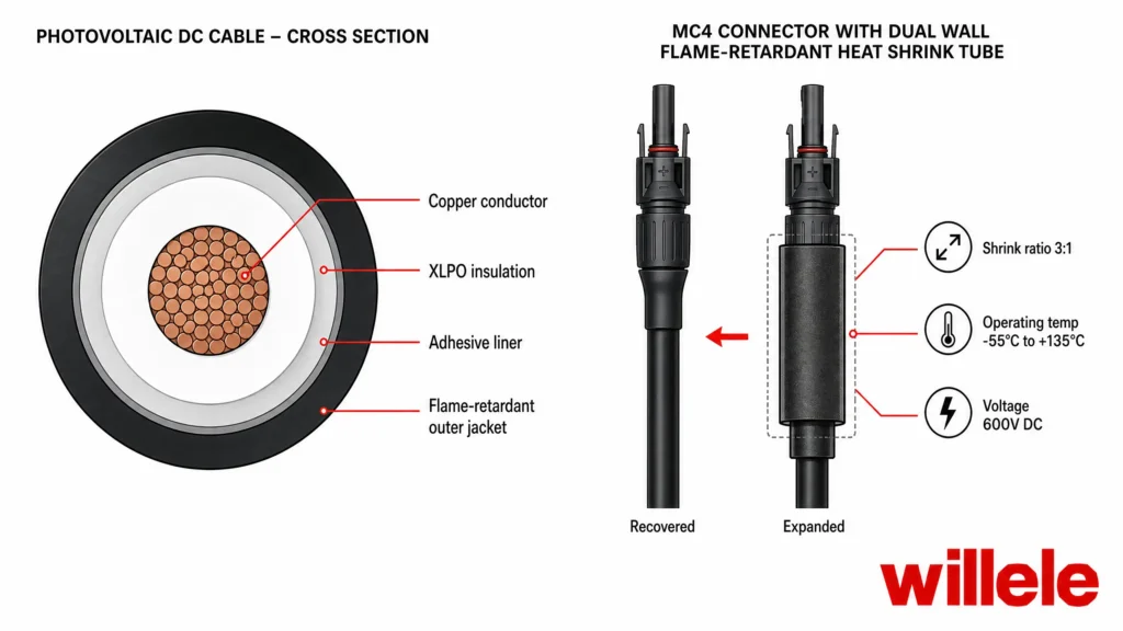
Figure 2 — Cross-section of a PV DC cable, and an annotated view of a dual-wall flame retardant tube recovering over an MC4 connector.
Where Heat Shrink Tubing Protects a PV Installation
Every exposed electrical joint in a solar plant is a candidate for heat shrink protection, but a handful of positions carry disproportionate risk. The connector-to-cable transition deserves particular attention: it is the point where a rigid connector body meets a flexible cable, concentrating mechanical strain, moisture wicking, and thermal cycling into a single short length. Module junction boxes, string combining, and inverter terminations each expose wiring to their own mix of heat, vibration, and weather. The table below maps the most common positions.
| PV location | What the tubing protects against | Typical specification |
|---|---|---|
| MC4 / connector-to-cable transition | Moisture ingress, strain, UV, abrasion | Dual-wall, adhesive-lined, 3:1, −55 °C to +135 °C |
| Module junction box and bypass-diode leads | Heat, vibration, moisture | Thin or medium wall, 2:1 |
| String combiner and DC combiner box | Cross-connection, abrasion, arc containment | Medium-wall, halogen-free |
| DC cable harness on racking | Chafe against rails and clips, UV | Thin-wall black, UV-stabilized |
| Inverter DC input and AC output terminations | Vibration, heat, moisture | Dual-wall, adhesive-lined |
| Roof and wall penetrations, BIPV edges | Water tracking, mechanical damage | Medium-wall, adhesive-lined |
Two details of PV topology shape how tubing is used. Because modules are wired in series, a single degraded joint affects the performance of the whole string and, in a fault, can expose adjacent conductors to unexpected voltage. And because many of these joints sit above an occupied structure, a failure is not only a performance loss but a life-safety event. The tubing specified at these points is therefore best chosen for the fault case, not the everyday case. Combiner boxes amplify the point: they concentrate many joints inside a single enclosure, so one failed termination can interrupt a whole string and put the enclosure’s interior at risk.
Selecting the Right Material for Solar Duty
Material chemistry sets the ceiling on what a tube can do. The four families below cover most solar work, and each carries a different balance of temperature range, flame behavior, weather resistance, and cost.
| Материал | Continuous temp. range | Flame behavior | UV / weather | Гибкость | Halogen | Typical solar use |
|---|---|---|---|---|---|---|
| Cross-linked polyolefin (XLPO) | about −55 to +135 °C | Self-extinguishing, low drip | Good when carbon-black filled | Высокий | Halogen-free grades available | General PV joints, harnesses, connector seals |
| ПВХ | about −55 to +105 °C | Strongly flame retardant | Moderate; can embrittle in UV | Умеренный | Contains halogen | Enclosures and cabinets, low-cost general use |
| Fluoropolymer (PTFE / FEP / PVDF) | up to about +200 °C and above | Excellent, very low smoke | Превосходно | Lower | Halogenated | High-temperature terminations, harsh chemical sites |
| Silicone | about −60 to +200 °C | Good; does not drip | Превосходно | Very high | Halogen-free | Flexible high-temperature and extreme-cold joints |
For most outdoor PV work, adhesive-lined cross-linked polyolefin delivers the best balance of performance, cost, and durability. It handles the full solar thermal range, resists UV when carbon-black filled, and forms a waterproof seal when heated. Fluoropolymer and silicone grades enter the picture only when a joint runs hotter than polyolefin can bear, or when extreme-cold flexibility is essential. PVC remains useful inside enclosures but is a poor choice for exposed rooftop duty, where UV and heat accelerate embrittlement.
When two candidates both appear to work, the deciding questions are usually environmental: how hot the joint will run in summer, how cold in winter, how much direct sun it will see, and whether the space below the roof is occupied. Price matters, but the cost of a failed joint — lost generation, call-out labor, and reputational damage — almost always exceeds the few cents saved on the sleeve.
Wall Construction and Shrink Ratio
Two structural decisions follow material choice: how thick the recovered wall should be, and how far the tube must shrink to grip its substrate.
| Construction | Sealing | Best suited to | Common shrink ratios |
|---|---|---|---|
| Thin-wall | Insulation and light abrasion only | Indoor harnesses, tight bundles | 2:1 |
| Medium-wall | Better mechanical and moisture resistance | Outdoor racking, combiner boxes | 2:1, 3:1 |
| Dual-wall, adhesive-lined | Fully sealed, waterproof joint | MC4 transitions, penetrations, buried runs | 3:1, 4:1 |
Sizing is where good intentions fail most often. Measure the outer diameter of the largest component the tube must pass over — usually the connector body — and the outer diameter of the finished cable beneath it. The tube must be large enough to slide over the connector and, once recovered, small enough to clamp the cable with meaningful contact pressure. When a wide gap separates those two diameters, choose a higher shrink ratio rather than a loosely fitting tube. A dual-wall tube should also be long enough for the adhesive to flow beyond the point of overlap at each end; a single-wall tube offers no such sealing and is best reserved for dry, indoor harnesses.
| Shrink ratio | Expanded : recovered | Choose when |
|---|---|---|
| 2:1 | Умеренный | Cable and connector diameters are close |
| 3:1 | Wide | A large connector body must pass over thinner wire |
| 4:1 | Widest | Irregular shapes and bulky transitions |
Matching the Tube to Climate and Region
Photovoltaic systems operate in nearly every climate on earth, and the tubing that thrives in one region can fail in another. Local conditions should drive specification as much as the electrical design does.
In hot, arid markets such as the Gulf States, North Africa, the US desert Southwest, and inland Australia, UV intensity and surface temperature reach their extreme. Here, carbon-black-filled XLPO or a fluoropolymer grade with a high upper temperature rating is the safer choice, and thin walls deserve caution.
In cold continental regions — Canada, Scandinavia, Northern Europe, and northern China — winter temperatures can fall well below −40 °C. Silicone or a low-temperature XLPO grade keeps its flexibility where stiffer materials would crack, and the recovered wall should never be over-stretched during installation.
Along coasts and in humid tropical markets, from Southeast Asia to the Gulf of Mexico and the Mediterranean, salt fog and constant moisture punish any joint that is not fully sealed. Adhesive-lined dual-wall tubing is the standard answer, because the melted adhesive physically blocks water tracking along the cable.
At high altitude, in the Andes, the Tibetan Plateau, or the Atacama, intense UV coincides with severe day-night temperature swings. A UV-stabilized, wide-temperature material — and generous attention to the recovered wall thickness — protects joints where the climate is at its most punishing.
The lesson is consistent: the keyword for safe PV tubing is not “fire resistant” but “fit for the site.” A tube that is over-specified for a mild climate only wastes money; one that is under-specified for a harsh one becomes a liability.
Installation Practices That Preserve the Flame Rating
A flame retardant tube only works if it is installed so that its material properties survive intact.
- Cut the tube cleanly and long enough to overlap both the connector and the cable by a comfortable margin.
- Clean and dry the substrate; oil, dust, or moisture trapped under the sleeve becomes the defect that later causes failure.
- Shrink from the center outward, working toward the ends, so trapped air escapes instead of forming voids. On dual-wall tubing, watch for the adhesive to soften and form a visible bead at each end.
- Stop as soon as the tube is fully recovered and its outline matches the substrate. Polyolefin is typically recovered around 120 °C; there is nothing to gain, and much to lose, by continuing to apply heat.
- Let the joint cool before bending or loading the cable.
Never shrink PV tubing with an open flame. A flame scorches and carbonizes the polymer, shrinks it unevenly, and can damage the cable insulation — while the conductive soot it leaves behind undermines the very protection you are adding. Use a controlled heat gun with a spreader nozzle.
Failure Modes to Avoid
Most field failures trace back to a small number of preventable mistakes: a recovered diameter too large to grip the cable, leaving a path for moisture; overheating that leaves the sleeve scorched and brittle; a UV-sensitive material used on exposed racking; adhesive that never fully flowed, so the joint was never truly sealed; or a tube stretched thin during a hurried installation. Each is a specification or workmanship error rather than a materials failure — which is precisely why disciplined selection and installation repay their cost many times over. All of them are avoidable with a defined specification, a trained installer, and a simple visual check once the joint has cooled.
Frequently Asked Questions
Is flame retardant heat shrink tubing the same as solar heat shrink tubing? No. All solar tubing should be flame retardant, but not all flame retardant tubing is built for solar duty. Solar grades add UV stabilization, a wider temperature range, and often a halogen-free, adhesive-lined construction suited to decades of outdoor exposure.
At what temperature should PV heat shrink tubing be shrunk? Common cross-linked polyolefin recovers at roughly 120 °C. Use a heat gun with a spreader nozzle and shrink evenly until the tube is fully recovered — never scorch it. Open flame is not recommended.
Can I use PVC heat shrink tubing on a rooftop PV array? PVC is strongly flame retardant and inexpensive, but it is less UV-stable and will embrittle under sustained sunlight and heat. For exposed rooftop and racking work, a cross-linked polyolefin or fluoropolymer tube is the more durable choice.
Why is adhesive-lined (dual-wall) tubing preferred at MC4 connectors? The connector-to-cable transition is where moisture wicks most easily. The adhesive liner melts to fill the gap between sleeve and cable, forming a waterproof, strain-relieving seal that a single-wall tube cannot provide.
How do I size heat shrink tubing for a PV connector? Measure the connector’s outer diameter and the cable’s outer diameter, then choose a tube whose expanded size slides over the connector and whose recovered size still grips the cable. Where the two diameters differ widely, select a higher shrink ratio.
Do flame retardant tubes replace arc-fault protection? No. Tubing is not an arc-fault device and does not replace proper system protection. What a correctly sealed, self-extinguishing sleeve does is remove the voids and moisture paths that allow many connector faults to start, while limiting the sleeve’s own contribution to a fire.
Building Safety Into Every Joint
Fire safety in a photovoltaic system is not won by a single heroic component. It is won joint by joint, at the small, unglamorous places where current, weather, and people meet. A correctly chosen flame retardant heat shrink tube — matched to the material, wall, shrink ratio, and climate of the site — turns each of those places into a durable, sealed, self-extinguishing connection that performs for the life of the array.
At willele, we manufacture flame retardant heat shrink tubing for photovoltaic and electrical applications, engineered around the material properties that solar duty demands. If you are specifying tubing for a rooftop, utility-scale, or building-integrated project, talk to our team about the grade that fits your environment — and your safety case.